Tool Range:
_________________________________________________________________________
Process of Aluminium shaping I
Discipline Related object - Polaroid camera
- draw and cut appropriate size of 1mm thick aluminium sheet
- Bashing the hammer (Nylon Bossing Mallet) against the sand bag to shape the internal dome shape.
To be honest, I did not know any general technique of metal shaping at the beginning. So I just blindly explored everything I could get in my hand (or see what others are doing)- I tried bashing the skin against sand bag (which is the most effective way); I tried using shrinker to brought in the edge of the surface, but it couldn't apply just at the inner surface where I wanted the dome shape to be- basically I just bashing the aluminium sheet against any concave shape trying to form the dome shape.... I was really lost for quite a long while. Therefore I don't have any idea how the initial dome (the photo above)came from.
I will mention the bowl shaping technique in the next skin shaping process.
I was lucky at that stage cause I got help from Peter. He saved me from my lost situation.
- I marked the aluminium skin into three layers
1. the exterior layer need to be flatten and smoothen out
2. the middle layer, which forms the camera lens, need to be brought in and form an cylinder shape.
3. the inner layer also need to be flatten and smoothen out
Meanwhile, the intersections of adjacent layers are quite obvious therefore the intersecting line needs further emphasising.
- 1. flatten the inner part of the aluminium skin and shape the lens' front edge.
Using the wedge hammer to smoothen the skin against cylinder metal mould.
- 2. shaping the cylinder camera lens section
Hammering the parameter of the lens' body. Controlling the angle between metal and mould meanwhile hammering the metal downward, which allows the front opening to shrink or extend.
- 3. Flatten the exterior layer using the same technique as "1"
- Comparing the aluminium skin with lasercutting model.
the exterior layer of skin needed to be further brought in
- In order to bring the skin closer to the template, I carefully marked the intersection part and started to give them more definition using steel hammer with sharp edge.
- Finally I enclosed the aluminium skin using trunk edge, shrinker and metal cylinder mould.
- the cracking is caused by over using of shrinker. It was hard to fix out. therefore I decided to trim the cracked skin off.
OUTCOME
_______________________________________________________________________
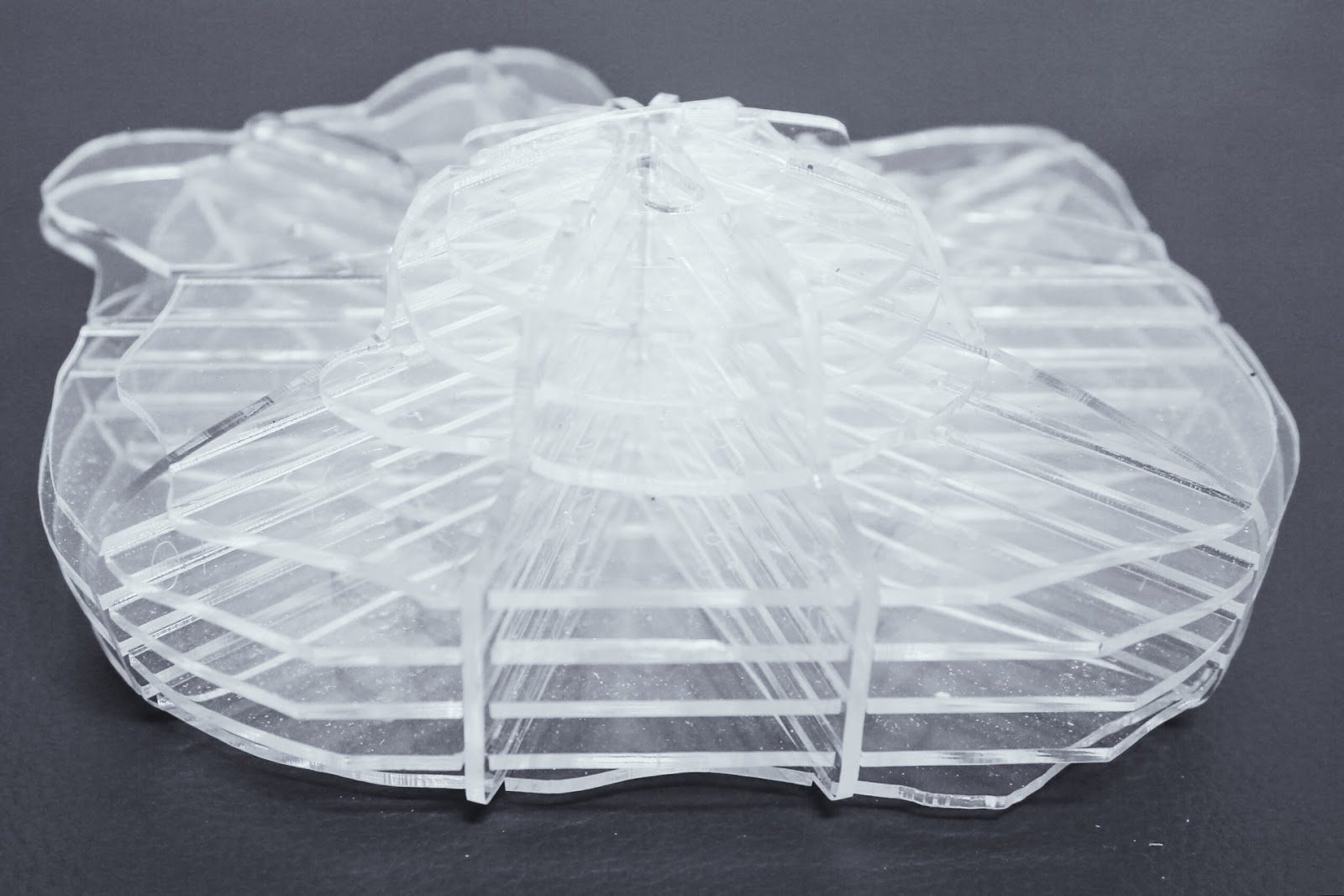
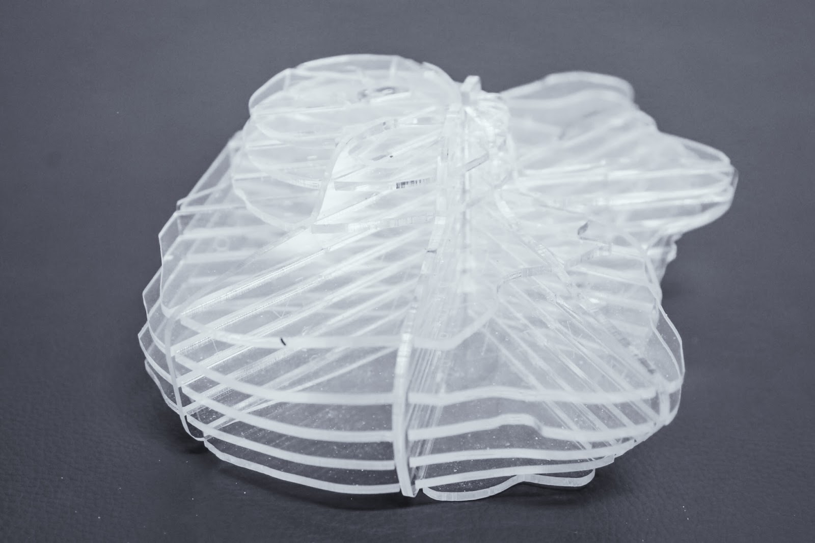
Process of Aluminium shaping II
Interdisciplinary skin - Hardhat
My second object is basically a squashed dome shape with edge stretching out. To avoid stupid attempt in shaping the skin, I asked Russell about the technique of making the dome before started doing anything.
The process of hardhat skin shaping is going to have 3 main steps:
1. general dome surface shaping
2. bringing up and shrinking the outer loop of skin in order adhere the skin closely to the template
3. extending the hardhat brim
- 1. general dome surface shaping
(The First Time of Shrinking)
I use the technique Russell told me to make the general bowl shape of my skin.
- bashing the aluminium really hard around the inner marking of circle
- bashing and pushing outward the outer plicated skin until the surface is curved and smooth
I found the surface is pretty large and stiff to work on with. It gave me a lot challenges throughout the skin-shaping process.
- 2. Further shaping the dome
I use the hemispherical mould and the hammer with the pitched head for further shaping of my aluminium skin.
(The Third Time of Shrinking)
At this stage I focus on shrinking diameter of the outer skin and make it steeper until shell could fit in. I lean the interior skin against the spherical tool with slight angle difference in between. Then hammer in an spiral circle around the aluminium.
As marked in the photo, the bowl shape needed to be largely brought in. The brought-in angle should go deeper as the surface came outward.
(The Fourth Time of Shrinking)
(The Seventh Time of Shrinking)
The skin started to come downward and fit the upper part of template edge.
change from the larger hemisphere metal mould to the smaller one
(The Eleventh Time of Shrinking)
I shape it over and over again and I even counted the time- I shrunk the whole skin for 11 times until it generally adhere to the shell. I was very frustrating in this stage cause it was repetitive, boring and took me such a long time.
The result turned out to be pretty good. Aluminium slowly have the shape I want. I just need to closing up the gap at bottom and working on brim part of the hard hat.
Detailing the skin until it closely adhere to the template
With the guide of Peter I closed gap at bottom part by marking the nonadhesive part and bash inward to the edge. I bashed left and right and then clean up the high point in the middle. The gap would be closed up by keep doing this.
But each time I did this the other part will be weirdly change at the same time. So I bash it, squeeze it, and did a lot stupid things until I felt satisfied with it.
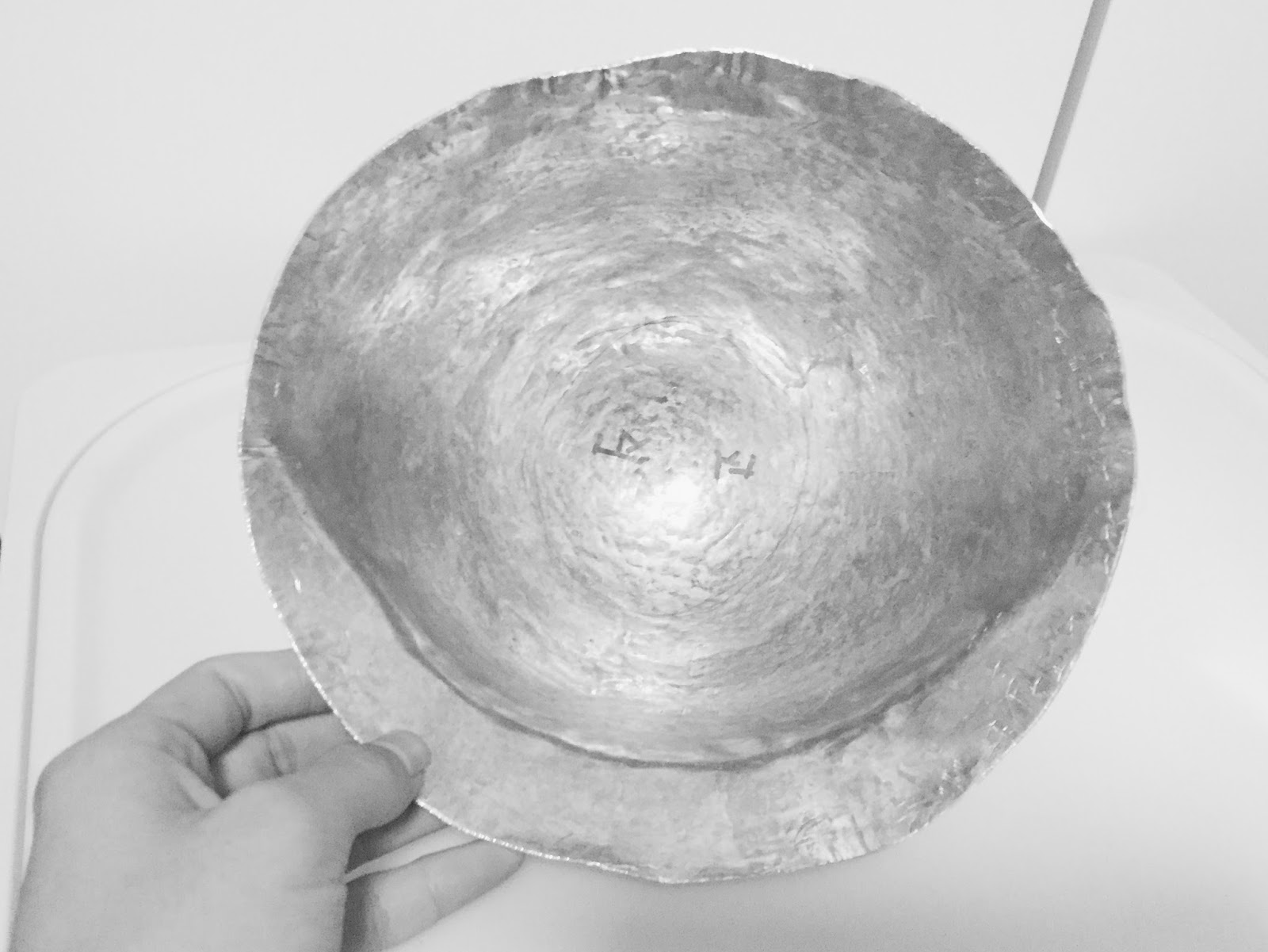
Polishing the aluminium skin with Methylated Spirites.
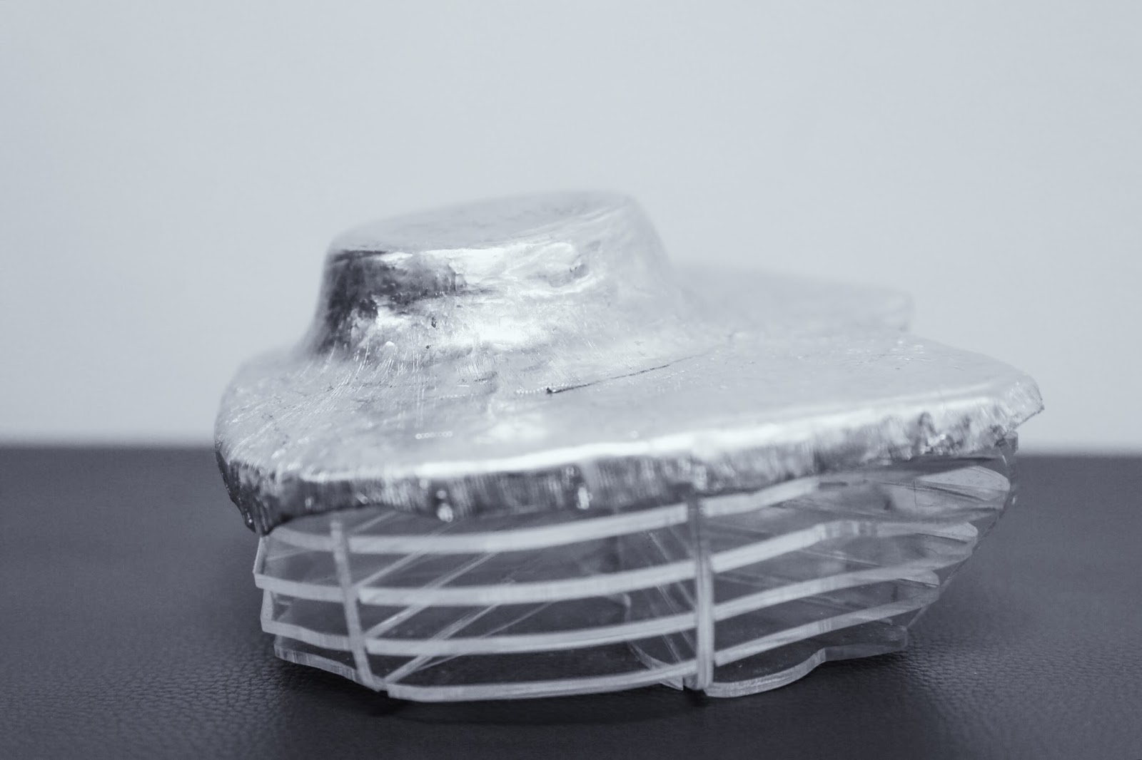
- 1. Hardhat brim shaping
Before started off, I trimmed the exterior crack loop that caused by shrinker.
It is indicated in the photo that the brim was made by squeezing the aluminium shape inward without hurting the other part of skin.
I leave the brim part to the last step.
I just shaped it by squeezing the aluminium inward and then use sharp head hammer to give the intersection line more definition.
The main difficulty of this aluminium skin is the work load of shaping quite large amount of surface. Because of that the control of the shape need to be more accurate when I shrunk and stretched the aluminium. The details of surface - sometimes open up slightly, sometimes close down steeply- therefore require precise observation, analysis and emphasis.
OUTCOME
_____________________________________________________________________
Reflection in shaping two different skins
When I chose discipline related object, the first though came to my mind is the camera. I made a lot of models for each semester. The sad thing is that because I often move my apartment so I will photograph them with my polaroid before I throw them out. This camera records my experience in architecture study.
Meanwhile, I like the idea of hardhat by Jason who is studying construction management. It is quite representative object when it comes to a construction manager who is working in the building site.
Both aluminium skins are made for regular, symmetry and dome-dominant object. The angle aluminium closing up or extending out determines the general shape of the skin. Although the start points (dome shape) are the same, the further shaping and detailing of the skin are significantly different.
The camera lens is pretty straight forward in terms of shape regularity- flat lens front+ cylinder lens body+ flat camera body. I learned how to extend or shrink the aluminium surface, which is the initial start point for dome-dominant shaping. When close up the metal to the edge of the template. I just need to get the accurate exterior shape of camera and use trunk edge to bring exterior aluminium skin downward. It was great to begin with in terms of basic metal shaping skills and the results turned up to be really well.

The hardhat, however, requires huge work load which I didn't expect at first. It became much more difficult when shaping the second aluminium skin. The full cover of template I decided to make need more patient when closing up the dome and detailing the enclosure of the shape. The details of the surface- sometimes open up slightly, sometimes close down steeply- require precise observation, analysis and emphasis. My skill of controlling aluminium shape got a huge improvement through the process of second skin making.
I made one mistake in both of the skin making which is the cracking caused by shrinker. For the first project, I was curious for shrinker therefore used it several times just for fun. But for the second project it just took me forever to close up the shape so in order to rush the dome shape, I used shrinker a lot. The only way to fix the crack is to trim the ceasmic part off. It is not good.
Overall I am glad to have chance to make two aluminium skin and I enjoyed the process of shaping my chosen objects a lot. From the dumb behaviour of trying to shape the dome using random hammer and concave mould at the beginning, until being familiar and patient with metal shaping process, I do make a difference through the learning of this course.
I remember in high school, my teacher made me to memorise "aluminium is a relatively soft, durable, lightweight, ductile and malleable metal". Now I understand how the aluminium is being soft, durable, ductile and malleable through the aluminium skin making. In the future architecture life, I got more understanding and confident to use when it comes to aluminium. Aluminium is widely used in architecture field, the purposes include lead, water pipes, roofing, window and even building facade. The better understanding of a material is essential for better and more successful architectural practice.
Some professional website about aluminium I'm using or studying these days:
aluminium info:
- http://aluminium.org.au/construction
- http://aluminiumleader.com/application/construction/
- http://www.aluminum.org/product-markets/building-construction
aluminium products:
- http://alucobond.com.au/product/alucobond-pe/
- http://www.alspec.com.au/